Sintronic Global:



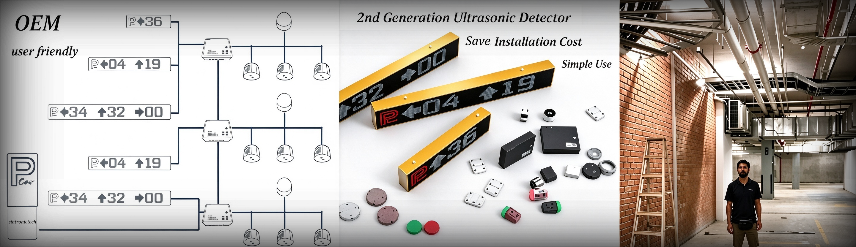
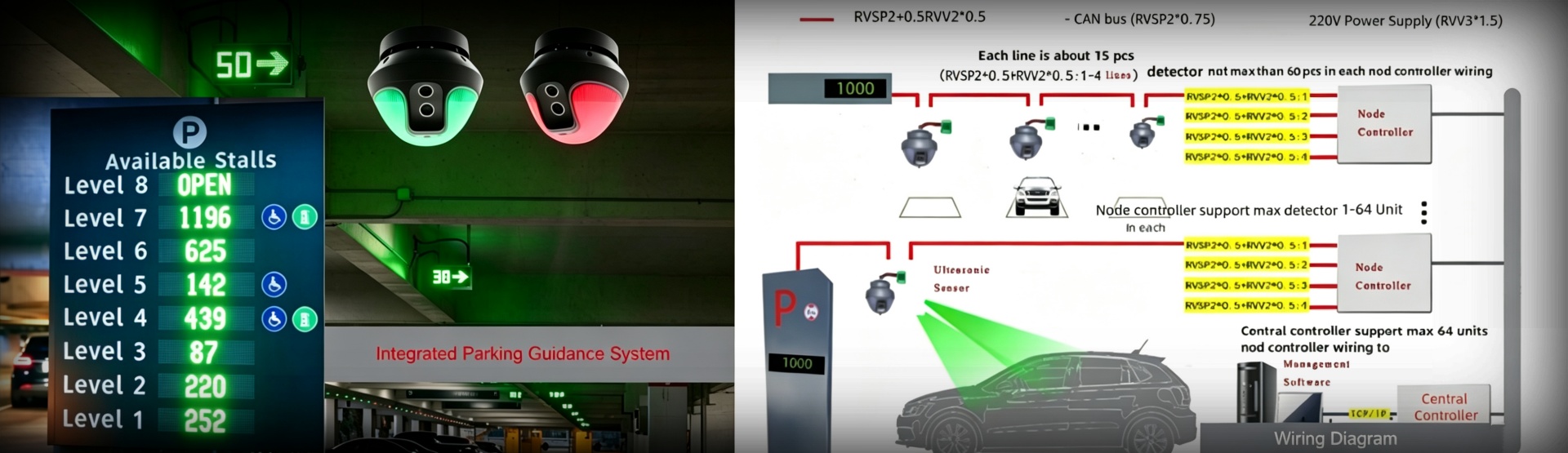
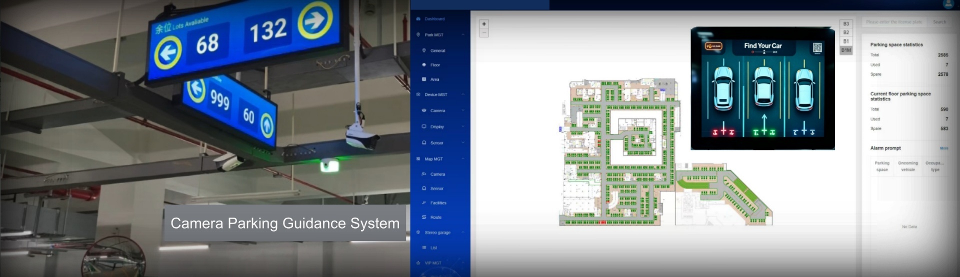
Sintronic camera detector (camera-based video detector) is ceiling-mounted vision-type sensing hardware for parking guidance system. Different from ultrasonic integrated or split detector which monitors only one single bay, one camera detector can cover multiple adjacent parking bays at one time. Its installation has strict requirements for field-of-view, mounting height, network wiring and camera-angle adjustment to guarantee accurate AI bay-status recognition.
Pre-installation Preparation
Complete below preparation before site construction:
1. Refer to project CAD drawing, confirm monitoring range for each camera detector, mark ceiling mounting positions. Make sure no heavy beams, ventilation ducts or large pipelines block camera field-of-view.
2. Prepare hardware: camera detector units, ceiling mounting bases, self-tapping screws, CAT5e / CAT6 network cable for TCP-IP, RVSP shielded twisted-pair cable for RS485, DC24V or PoE power supply, PGS node / central controller, PoE switch.
3. Tools: electric drill, screwdriver, safety ladder, multimeter, network cable tester, laptop for camera IP access and parameter configuration.
4. Hardware inspection: check camera detector appearance, lens and connectors for damage caused during transportation.
Installation Position & Height Requirements
Camera detector performance heavily depends on correct mounting position and clear field-of-view.
1. Mounting Height: Recommended installation height 2.2-3.5m above ground, optimal height range 2.5-3.0m. Height shall match actual monitored bay quantity.
2. Position Rule: Install overhead above the middle zone of target parking bays. Ensure camera lens can capture full view of all monitored parking spaces.
3. Obstruction Avoidance: Keep lens away from shelter of beams, pipes, lamps. Avoid strong direct light shining into camera lens, which will affect AI image recognition accuracy.
4. View Coverage: Confirm each camera’s monitoring scope matches project design; do not let parking bay edges go outside camera image frame.
Important note: Camera detector is NOT suitable for zones heavily blocked by dense ceiling obstacles; choose integrated or split ultrasonic detector for those areas.
Step-by-Step Installation Procedure
1. Align mounting base on pre-marked ceiling position. Drill holes and fasten firmly with self-tapping screws. The mounting surface must bear at least 3 times total weight of camera detector unit.
2. Reserve cable hole for network cable and power cable passing through the base. Keep base horizontal and stable without shaking.
1. Pass power cable and network cable through reserved hole of mounting base.
2. Lock camera detector onto mounting base securely. Pull slightly to confirm it will not drop.
3. Adjust camera lens angle: tilt and rotate camera, make sure all target parking bays fall inside camera field-of-view. Tighten angle-locking screws after adjustment.
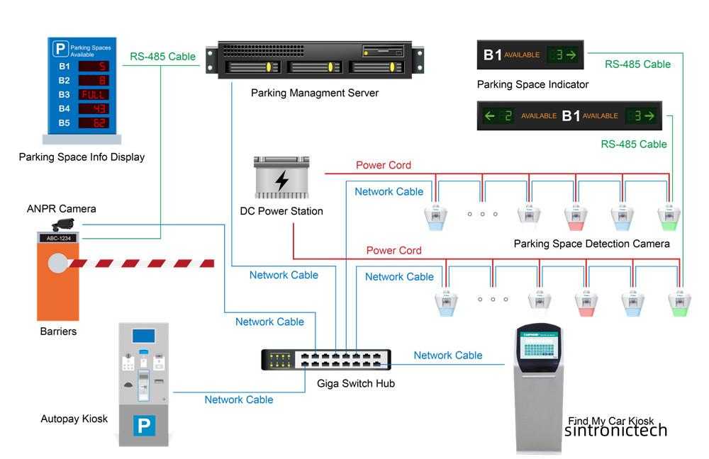
SintronicParking camera detector supports dual communication: TCP-IP (PoE optional) and RS485 bus.
1. TCP-IP Connection: Use CAT5e / CAT6 network cable, connect camera LAN port to PoE switch. Switch further links to PGS central controller or on-site management laptop. Maximum cable length shall not exceed 100 meters.
2. RS485 Bus Connection: If adopting RS485 bus mode, use RVSP shielded twisted-pair cable, follow daisy-chain hand-in-hand wiring. Do not use star-shaped topology. Do single-end grounding for cable shield layer.
3. Power supply: Support DC24V external power or PoE power input. Double-check power specification to avoid burning device.
1. Connect laptop to same local network, access camera detector via default IP address through web browser.
2. Modify camera IP address, gateway and subnet mask to match on-site PGS network segment. Record IP corresponding to monitored bay numbers for later software debugging.
3. Set monitored parking-bay quantity and ROI region inside camera web interface; calibrate each bay boundary for AI vision algorithm.
4. Set LED indicator logic: confirm LED turns green for vacant bay and red for occupied bay.
1. Double-check all power and communication wiring to prevent short-circuit risk, then power-on the camera detector.
2. Camera runs automatic initialization; LED indicators will flash briefly during boot-up.
3. Simulate vehicle-parking test: place obstacle inside each monitored parking bay. Verify LED status changes correctly between red and green.
4. Log in PGS-SW parking guidance management software. Confirm camera detector goes online normally and uploads real-time multi-bay occupancy data.
5. Fine-tune camera angle and algorithm sensitivity if mis-detection occurs.
Key Installation Notes
1. Lens must keep clean during installation; do not scratch camera lens surface.
2. Keep network cable within 100-meter limit for PoE / TCP-IP transmission. Use qualified shielded network cables.
3. Mixed deployment is supported: camera detector can work together with integrated detector or split detector under same PGS system. Every device needs unique IP or device address.
4. For humid underground parking garages, keep all connectors away from water vapor and moisture.
5. Do not install camera detector facing strong light source; strong glare will cause frequent false detection.
Contact: Tim Wu
Phone: +86-15813805304
Tel: +86-15813805304(whatSapp)
Email: infors@sintronictech.com
Add: Pengrunda Commercial Plaza 32101,NanShan Area,Shenzhen
 Whatsapp