How to install Split Detector for Parking Guidance System?
Sintronic split detector package consists of two independent units: ultrasonic detection unit and separate red‑green LED indicator. Unlike integrated detector, sensor and indicator can be mounted at different ceiling positions, which fits complex ceiling beam and pipe layout in large multi‑zone underground parking garages.
This article covers full workflow: pre‑installation preparation, position‑height requirements, mounting for detector & indicator, inter‑unit wiring, RS485 bus connection, address configuration, power‑on commissioning and field troubleshooting.
Pre‑installation Preparation
Complete these checks before site construction:
-
Review project CAD drawings, mark mounting points for ultrasonic detector and matching LED indicator for each parking bay.
-
Prepare hardware: split detector sets, mounting bases, self‑tapping screws, RVSP shielded twisted‑pair cable (for RS485 bus), signal cable between detector and indicator, DC24V power supply, PGS node controller.
-
Tools: electric drill, screwdriver, safety ladder, multimeter, PGS handheld remote controller for parameter setting.
-
Inspect hardware: confirm no damage for ultrasonic detector unit and LED indicator during transportation.
Installation Position & Height Requirements
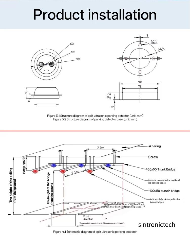
Split detector has separate position rules for detection unit and LED indicator.
-
Ultrasonic detection unit
-
Mount vertically overhead right above the center of parking bay.
-
Recommended installation height: 2.0‑3.0m, optimal height 2.5m.
-
Ultrasonic probe must face straight downwards, keep away from ventilation ducts, pipelines and hanging obstacles which may interfere ultrasonic echo.
-
Separate LED indicator
-
Install above the front edge of parking bay line, for drivers to easily view red/green status light.
-
Horizontal offset from parking bay front line: 0.3‑0.5m, allowable range 0‑1.0m.
-
Keep indicator unobstructed without shelter from beams or pipes.
Important note: One ultrasonic detector matches one dedicated LED indicator, do not cross‑connect different sets.
Step‑by‑Step Installation Procedure
Step 1 Mount ultrasonic detection unit
-
Fix mounting base at pre‑marked ceiling position with self‑tapping screws; keep base horizontal and firm.
-
Pass power & RS485 bus cable through base cable hole.
-
Lock ultrasonic detector unit onto base, pull slightly to confirm it is securely fixed and will not drop.
Step 2 Mount separate LED indicator
-
Fix indicator mounting base at the front‑edge position of corresponding parking bay.
-
Run signal cable between ultrasonic detector unit and LED indicator. Make cable route neat along ceiling beams or cable tray.
-
Lock LED indicator onto its base, ensure indicator light surface faces down for clear visibility for drivers.
Step 3 Internal wiring: detector to indicator
Connect dedicated signal cable between ultrasonic detection unit terminal and LED indicator terminal. Wrong wiring will cause indicator fail to switch red/green status.
Step 4 RS485 daisy‑chain bus wiring
-
Use RVSP shielded twisted‑pair cable for DC24V power and RS485‑A / RS485‑B communication.
-
Adopt hand‑in‑hand daisy‑chain topology. Do NOT use star‑shaped wiring which causes unstable bus communication.
-
The first split detector on each branch connects to corresponding port on PGS node controller.
-
Do single‑end grounding for shield layer of RS485 cable to reduce electromagnetic interference.
Step 5 Set unique physical address
Every split detector set requires exclusive address within same node controller branch.
-
Option 1: Configure address via handheld remote controller from ground, no climbing ladder needed.
-
Option 2: Set address through DIP switch on detector back‑side.
-
Record address number mapping to each parking bay number for later software debugging.
Step 6 Power‑on and on‑site commissioning
-
Double‑check all wiring, avoid short‑circuit risk, then switch on DC24V power supply.
-
Detector and indicator run self‑initialization; LED will flash briefly.
-
Adjust ultrasonic detection distance / sensitivity by remote controller according to actual installation height.
-
Simulation vehicle test: place obstacle below ultrasonic detector. Verify indicator status switch: Green for vacant bay; Red for occupied bay.
-
Log in PGS‑SW parking guidance software, confirm split detector goes online normally and upload real‑time bay occupancy data.
Key Installation Notes
-
Sensor and indicator can install at different positions to bypass complex ceiling beams, but keep one‑to‑one matching for each parking bay.
-
Do not mix‑up A/B terminals of RS485 bus; swapped A/B line leads to device offline.
-
Each PGS node controller supports limited quantity of split detector sets, follow hardware specification, do not overload single branch.
-
Mixed deployment supported: split detector can work together with integrated detector on same node branch, all devices must keep unique address.
-
For humid underground parking garage, keep all wiring terminals away from water and moisture.
Troubleshooting After Installation
|
Symptom
|
Possible Cause
|
Suggestion
|
|
Detector powered on, but LED indicator no light
|
Wrong inter‑connection cable between detector & indicator
|
Re‑check wiring between ultrasonic unit and LED indicator
|
|
Indicator light works, but no data uploaded to PGS‑SW
|
RS485‑A/B reversed or duplicate device address
|
Swap RS485 A‑B wire; reset unique detector address
|
|
Frequently false detection (wrong occupied / vacant status)
|
Improper installation height or surrounding obstructions
|
Adjust mounting height; remove obstacles above parking bay
|
System Compatibility
Sintronic split detector package is fully compatible with complete PGS ecosystem:
-
PGS node controller & central controller
-
Indoor LED available‑space guidance display boards
-
PGS‑SW parking guidance management software
-
Can be mixed‑installed with integrated detector for hybrid PGS projects.
Reference real‑world project: 1500 bays Split Parking Guidance System‑Zimbabwe
Technical Support
As dedicated PGS hardware division of Sintronictech, Sintronic offers installation drawing, wiring diagram, datasheet and remote technical support for global integrators and contractors. Contact our sales team for project‑level technical guidance and quotation.



 Whatsapp