Language:


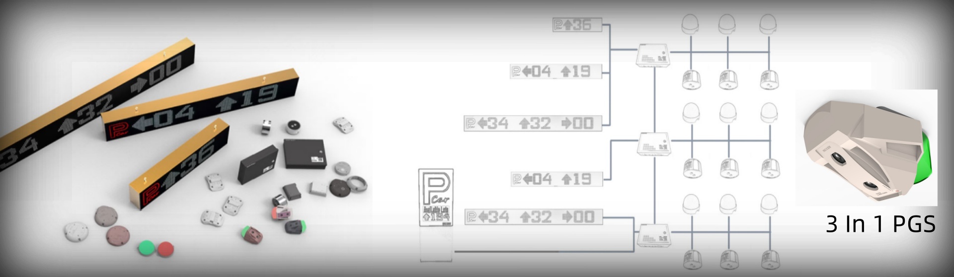

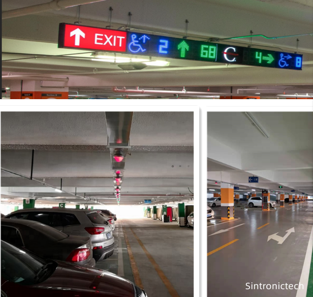
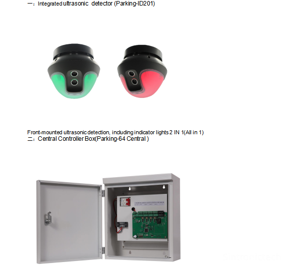
All in 1 Parking Guidance System means 1 unit of parking guidance detector integrated with
indicator all in 1 , the detector can both work as detector and indicator.
As when there is a car in the parking bay the detector will turn to red color otherwise it will be green color.
2.Working Principle
>一. Parking Lot Detector (PD) constantly detects the presence vehicle
By using Ultrasonic wave, if any vehicle is parking on the space, PD will send
command to Parking Lot Indicator
>二. In the same time PD will immediately transmit its status to Area
Controller Module (ZCU) and processing the data and send to
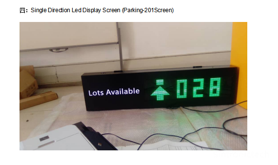
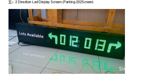
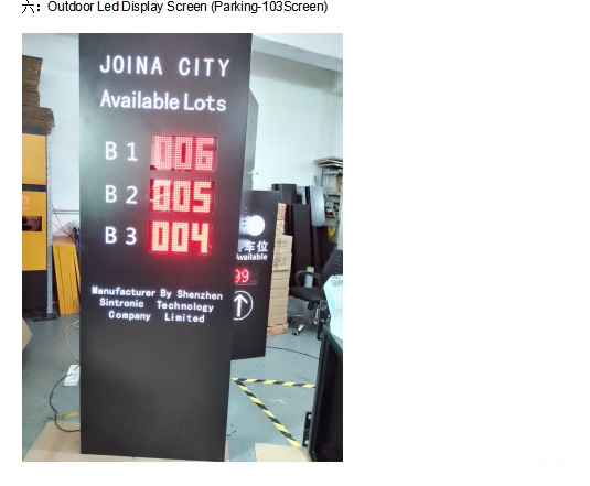
Parking Guidance Display Screen (Display).
>三. Parking Lot Detector, Led Display Screen and Vehicle Detector to make the whole system which can run offline independently.
>四:The main controller can collect all the system data and display on the pc software by
Using TCP/IP protocol which in physical port is rj45.
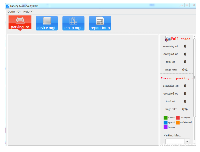
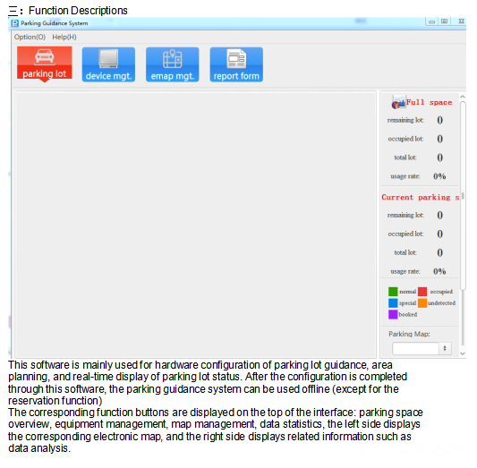
>五. The System Management Software have below functions:
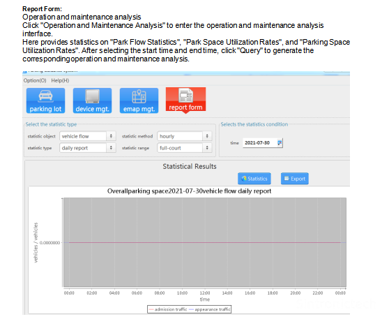
1). Feedback the real time occupancy situation to the control room.
2). Parking spaces usage statistics and reports
3).parking spaces number correction
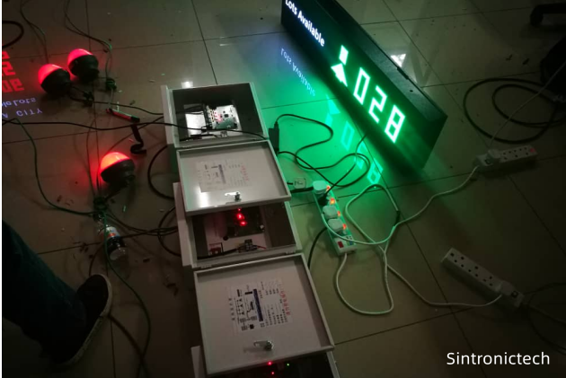
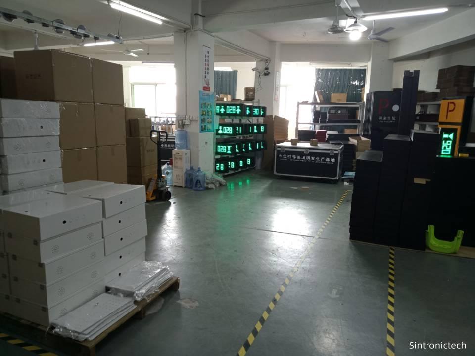
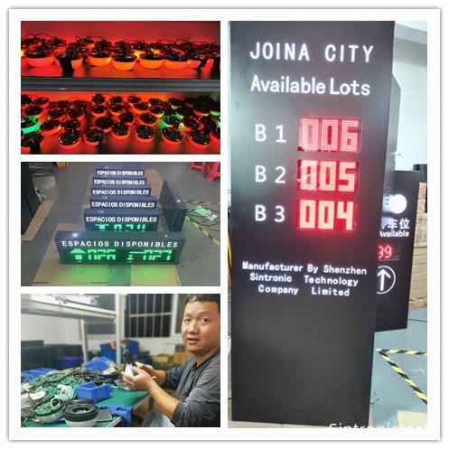
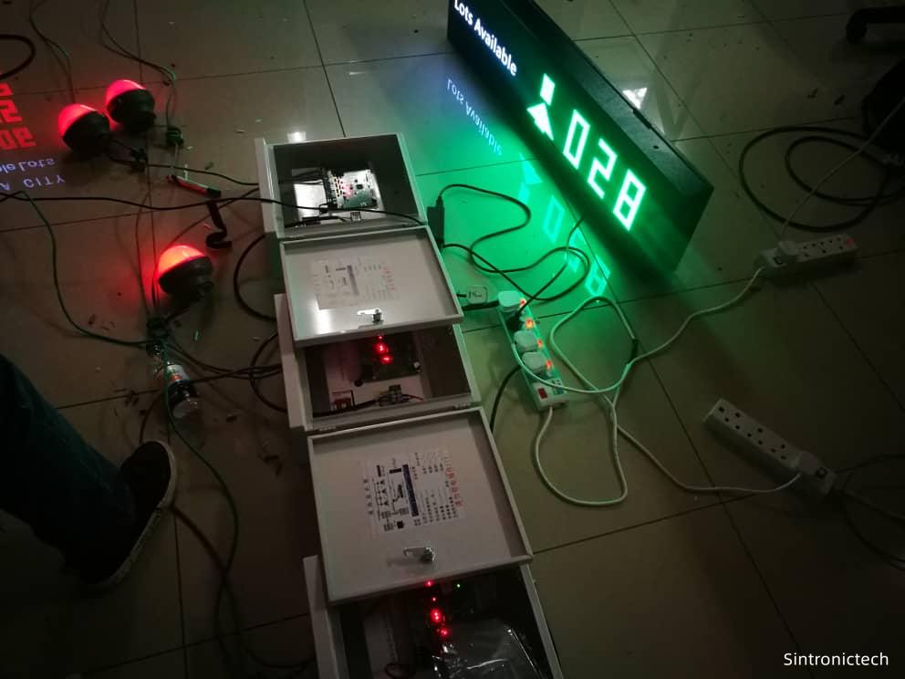
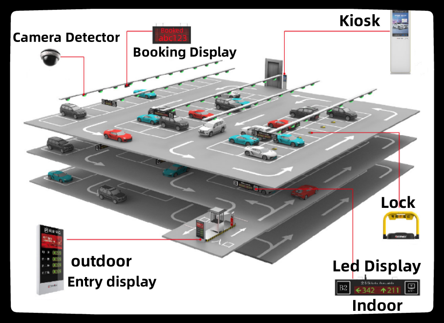
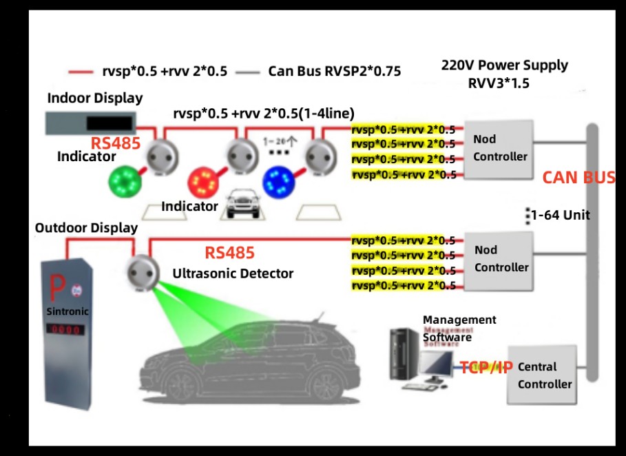
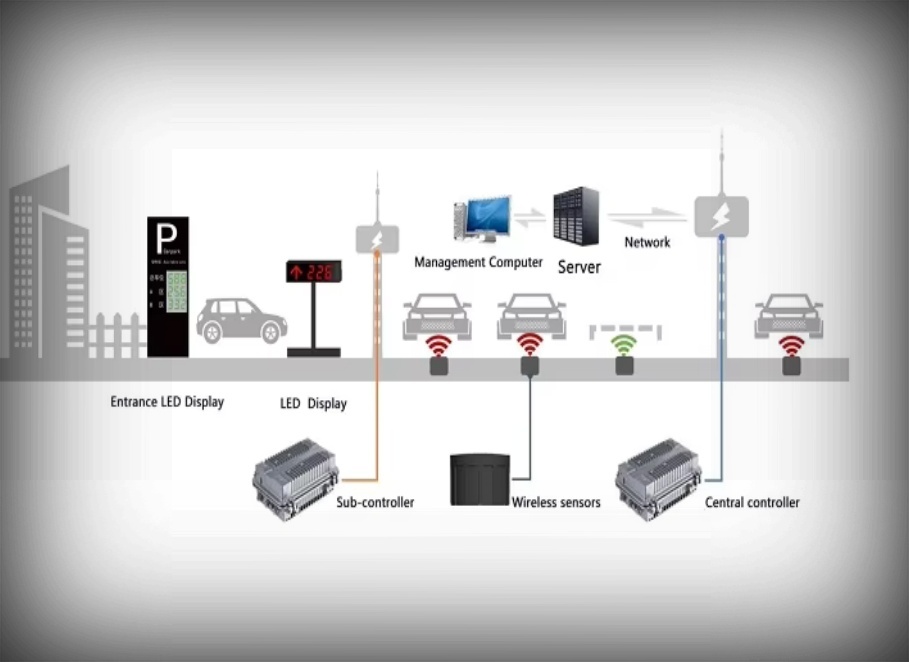
3.System Components
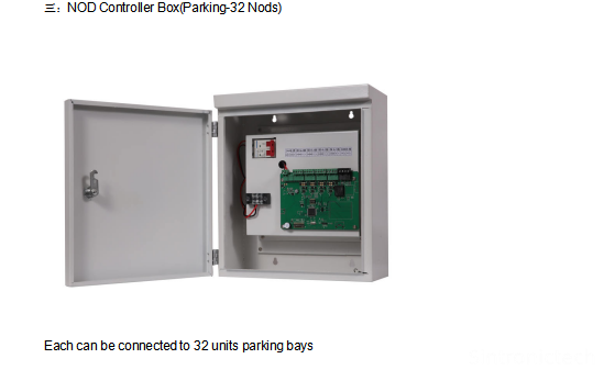
Independent offline control and one unit of main control box can support max 64 units of nod control box
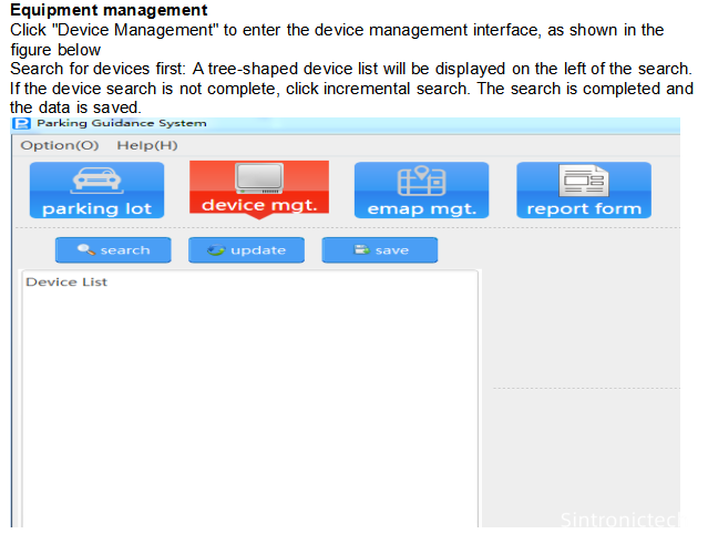
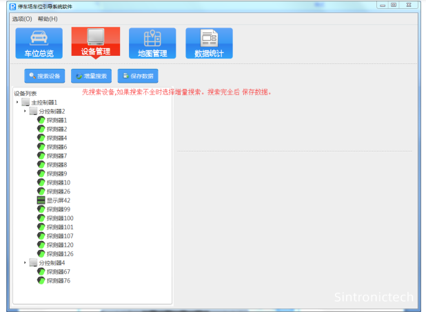
4.Management Software
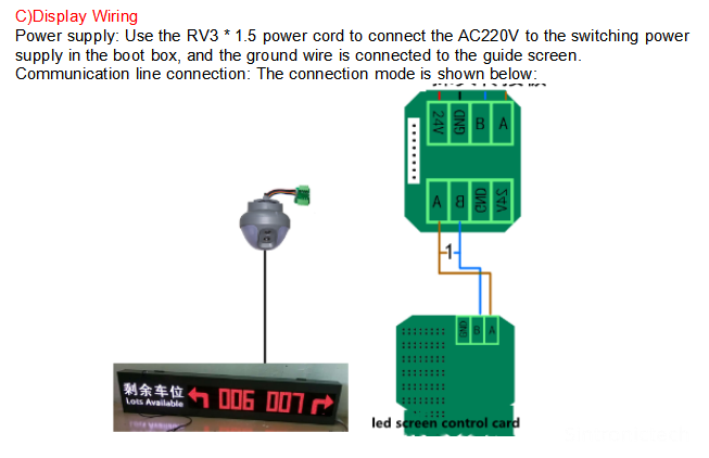
5.Power supply
1.The system use DC 12V power supply for the device power input.
2.Detector and led display wiring use rs485 communication cable
3.Central controller wiring to PC management software use TCP/IP communication
4.Central controller wiring to nod controller and in between nod controllers it use the cab bus
Wiring method
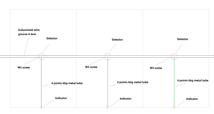
6.Project Installation Guide
Requirement:
1. The installation height of the parking space detector must not be lower than the parking lot limit;
2. There must be no other hanging objects around the parking space detector;
3. The parking space indicator is consistent with the projection of the projection and the parking space end, and there must be no obstacles in front;
4. In front of the guidance information screen, if there are obstacles such as air -conditioning ducts, water pipes, fire water pipes and other obstacles, the corresponding movement screen position should be moved according to the premise of ensuring the guidance effect, which can be determined according to the construction guidance.
Wiring Description
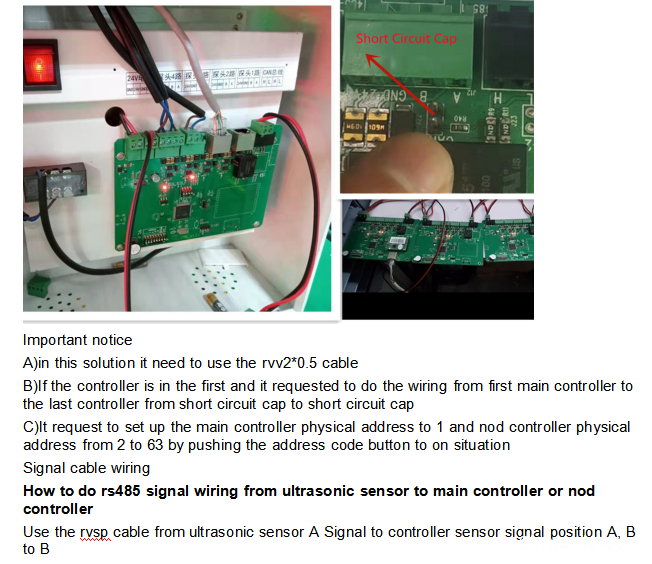
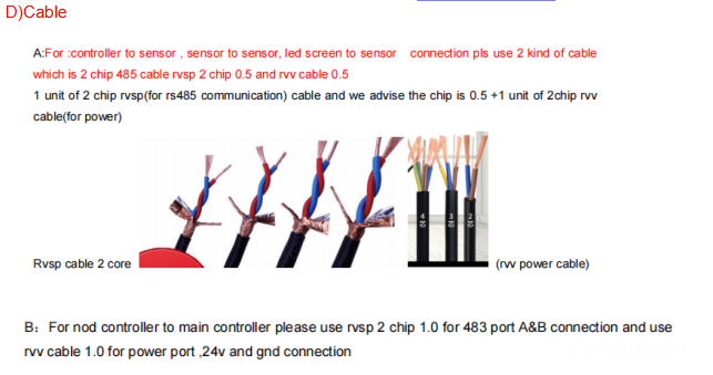
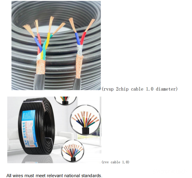
1.The power cord of the parking space detector adopts RVV2X0.5mm+RVSP2*0.5 wire(1-4 lines), and the parking space detector communication cable adopts
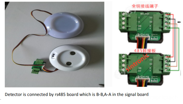
A)Detector wiring:
Our ultrasonic sensor for parking guidance system adopt rs485 communication technology to work for each other signal transfer and it request to use the RVVPS cable for wiring by doing like
orange+white (line order)for connecting to A and Orange color for connecting to B
Or green+white wiring to A and green wiring to B
B)Controller wiring
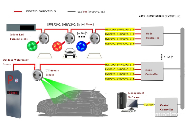
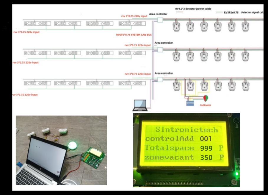
Central controller wiring to nod controller and in between nod controllers it need to use the can bus RVV3*1.5+RVSP2*.075
For example
1 unit of Our Main controller support 4 line ultrasonic sensor wiring and each line can support about 30 unit of
Power wiring
ultrasonic sensors and the main controller is connecting to nod controller by using the can bus port which is H ,L,H,L
which is wiring one by one from H to H, L to L
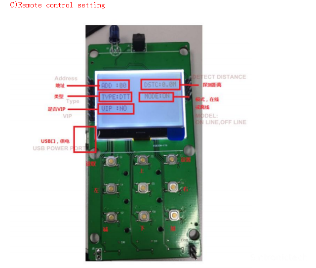
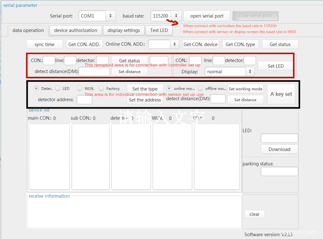
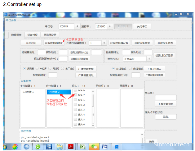
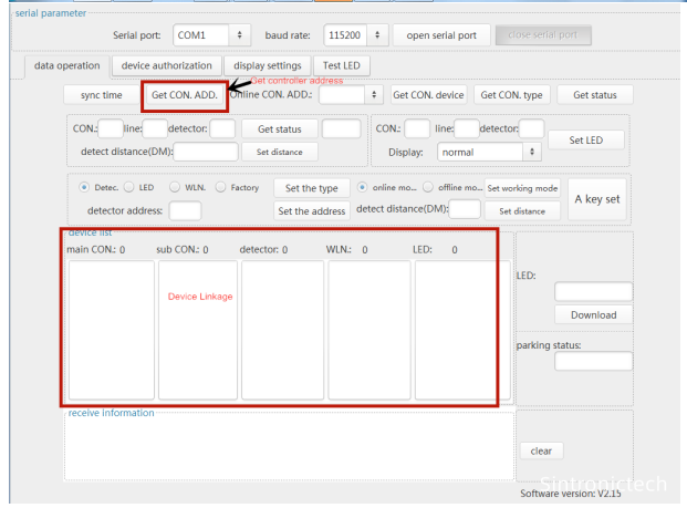
1. Address: Set the address code
2. Detection distance: 0-6M can be set
3. Equipment type: can be set to probe (DTT), screen (screen), wireless light (light) (not used temporarily)
factory test mode (factory)
4. Working mode: offline (off) or online mode (on). In online mode, if there is no RS485 connection within
one second, the LED will flash. Offline mode does not flash
5. Display type: Normal mode (red and green display), whether it is VIP (red and blue display), and
appointment mode (red and yellow display). Up, down, left, and right are used to select which parameter
to set, and the cursor will flash on the currently set value. The plus and minus keys change the parameter
value. The read key can read the current information of the device. After setting the parameters on the
screen, click the setting button to set the corresponding parameters of the device.
2.All communication cables in the system must adopt the bus wiring method. It is strictly forbidden to adopt a star or "T" forming method.
3. All strong and weak electricity are wiring. The wiring and installation of the parking space detector are installed in a wire groove. The specifications of galvanized wire grooves are 50mmx25mm and the thickness of 0.8-1mm;
4. This system's AC220V power supply should be set up with lightning protection and grounding measures. The system line must set up a leakage circuit breaker protection.
5. The electrical equipment of this system, metal shell, cabinet (frame), metal tube groove, shielding cable outer layer, anti -static grounding of information equipment, safety protection grounding, wave surge protector (SPD) grounding end, etc. The grounding terminal connection with the equal potential connection network.
6. The parking space detector should be installed above the center of the parking space. Except that there are restrictions on the top spot, it should be consistent (local limit height and the distance between the vehicle should not be less than 500mm)
7. The parking space detector and parking space indicator are installed at the same level. According to the situation at the scene, the best distance is 2.3 meters to 2.5 meters (where the local area is not enough can be appropriately reduced); Other objects are blocked; vertical installation is directly above the parking space.
8. The parking space indicator can be localized when encountering obstacles such as air ducts. In case of obstacles such as the tube row, air duct, etc.
(1) If the upper obstacles are parallel to the indicator light, the height of the indicator light is used;
(2) If the obstacle of the upper obstacle is crossing the arm of the indicator light, the indicator lighting arm support is consistent with the height of the height of the height of the indicator light after bypassing the obstacles. In order to ensure the overall aesthetics, more than two elevations should not occur at the same position.
9. The parking space indicator is consistent with the projection of the projection and the end line of the parking space; in the case of a local decline area, the line tube of the parking indicator light should be unified with the standard high after 90 degrees.
10. Guide the information screen divided into the total screen and regional guidance information screen. The total screen is installed at the main entrance of the parking lot. It should avoid the sun and rain as much as possible. The lowest point of the height screen is higher than the limit of the parking lot. The stainless steel rope with a diameter of 3mm-4mm is hanging vertically above the intersection.
11. In order to avoid damage or failure caused by intentional or unintentional touch, the regional controller should install as much as possible on the wall with a height of no less than 2 meters from the ground.
12. Other unruly places, refer to construction guidance or relevant industry standards.
7.System structure diagram
9.Software
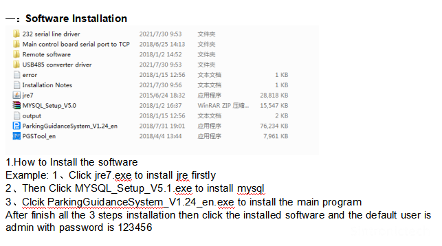
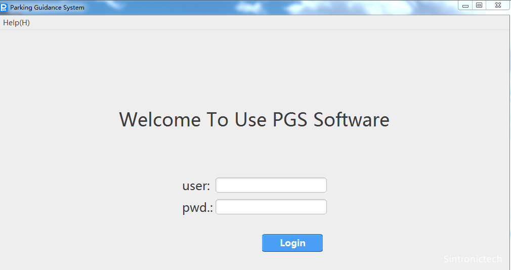
二:Controller and Detect sensor and Display Screen Set Up
1.Double click PGSTOOl_en
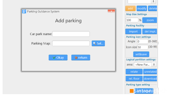
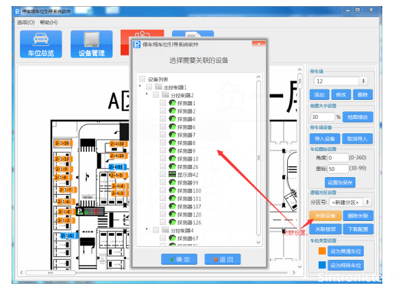
Map management:
Add electronic map to name the map name
Map zoom: adjust the map to fit the size
Import device: Import the device that has been saved before. One-click import or selective import of some devices
The device import port is displayed in the upper left corner of the software, hold down the left mouse button and drag the icon to the corresponding position
Parking space icon settings: Imported device icons can be selectively adjusted in size and angle
Contact: Tim Wu
Phone: +86 15813805304
Tel: Number Above Is For Whatsapp&Wechat
Email: infors@sintronictech.com
Add: No.3368,Pengrunda Commercial Plaza 32101,Rd Houhaibing,Haizhu District,Yuehai Street,NanShan Area,Shenzhen City
 Whatsapp