How to make installation of the integrated detector in parking guidance system?
An integrated detector is the all‑in‑one ultrasonic bay‑sensor with built‑in RGB LED indicator for parking guidance system (PGS). Correct installation directly decides vehicle‑detection accuracy, stable RS485 bus communication and long‑term service life for underground or semi‑open parking lots. Improves mounting height, wrong wiring or incorrect DIP‑switch address will cause false detection, communication drop‑off or LED indicator failure. This article provides complete site‑survey, mechanical mounting, wiring, address configuration, commissioning and troubleshooting workflow for system integrators and field technicians.
Pre‑Installation Site Survey & Preparation Work
Before physical installation, complete site assessment and material preparation to reduce on‑site rework:
-
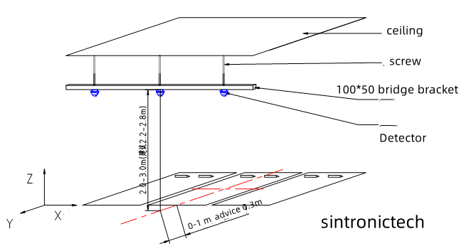
Measure ceiling height: Recommended mounting height range 2.0‑3.0 m, optimal height is 2.5 m. Avoid installation higher than 3.2 m or below 1.8 m, which will trigger frequent mis‑detection.
-
Mark parking‑bay center position: Each integrated detector must be mounted vertically right above the geometric centre of one parking bay. Horizontal offset shall be controlled within 0.3‑0.5 m from bay centre.
-
Check obstacles: Keep away large beams, ventilation ducts, metal pipelines. Obstacles will reflect ultrasonic wave and generate false occupancy signals. Maintain ≥60 cm horizontal spacing between adjacent detectors to prevent ultrasonic mutual interference.
-
Hardware & tool preparation: Integrated detectors, node controllers, shielded RS485 twisted‑pair cables, ceiling mounting brackets, DIP‑switch adjustment tool, multimeter, cable conduits.
Core Components Check before Mounting
Check every integrated detector unit before installation:
-
Ultrasonic transmit‑receive probe surface free of scratch or dust contamination
-
RGB‑LED indicator function intact
-
DIP‑switch address setting terminals accessible
-
RS485 power‑signal terminals without loose pins
-
Matching ceiling‑mount bracket and fixing accessories complete
Step 1: Mechanical Ceiling‑Mount Installation
-
Fix special mounting bracket firmly on ceiling or bridge frame above parking bay centre, ensure bracket bears enough weight for detector unit.
-
Fasten integrated detector onto mounting bracket. Keep detector probe surface pointing vertically straight down toward parking ground, no tilt angle. Tilt installation is the top cause of false detection.
-
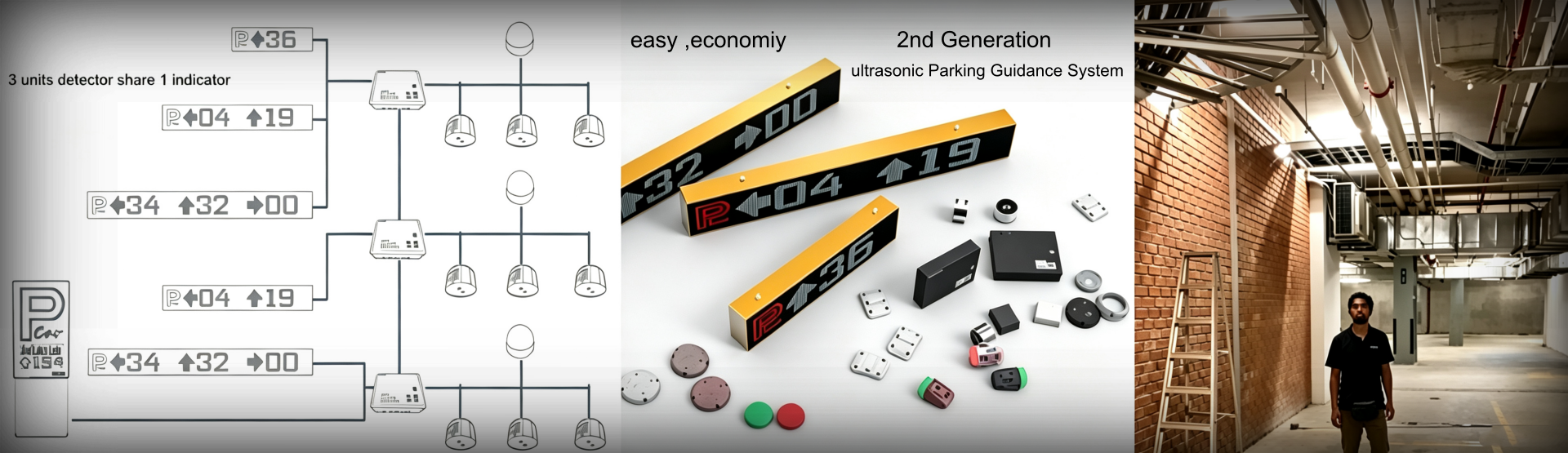
For multiple bays: Follow parking‑lot zone division, arrange detector sequence according to node‑controller bus grouping. One Sintronic node controller supports maximum 60‑64 integrated detectors per RS485 bus channel.
-
Reserve reasonable maintenance space for later inspection or unit replacement.
Important note: Do not apply paint, glue or spray coating onto ultrasonic probe membrane, coating will block ultrasonic signal and damage detection performance.
Step 2: RS485 Daisy‑Chain Cabling Work
Sintronic integrated detector adopts RS485 daisy‑chain bus topology, star‑type wiring is strictly forbidden.
-
Use shielded twisted‑pair RS485 cable: one pair for A/B communication signal, another pair for DC24V power supply. Run cables inside PVC / metal conduit for dust‑proof and rodent‑proof protection.
-
Daisy‑chain connection rule: Connect output terminal of previous detector to input terminal of next detector in sequence. The final end‑of‑line detector connects back to node controller RS485 port.
-
Wiring terminal definition:
‑ VCC / GND: DC24V power input
‑ A / B: RS485 differential signal, strictly avoid A‑B reversal
‑ Cable shield layer: Single‑end grounding at node‑controller cabinet side; do not double‑end grounding to prevent ground‑loop noise.
-
Max bus length per channel ≤300 meters. If distance exceeds limit, add additional node‑controller or signal repeater.
-
After wiring complete, use multimeter to check power voltage and A‑B signal continuity before power‑on.
Step 3: DIP‑Switch Unique Address Configuration
Every integrated detector on same RS485 bus must be assigned a unique physical address, duplicate address leads to total bus communication failure.
-
Open detector housing cover to access DIP‑switch block.
-
Set binary DIP‑switch to assign distinct address number for each unit under same node‑controller channel. Address range 0‑63.
-
Record bay number and corresponding detector physical address on project as‑built drawing, convenient for later troubleshooting and maintenance.
-
After address setting finished, close detector housing and fasten screws to guarantee dust‑proof performance.
Step 4: Power‑On and On‑Site Commissioning
-
Supply DC24V power to node‑controller and whole RS485 detector bus.
-
Observe indicator status:
‑ Normal communication: Detector blue heartbeat LED flashes periodically.
‑ No‑communication fault: LED keeps static‑off or steady‑on; re‑check wiring polarity and DIP address.
-
Real‑bay functional test:
‑ Empty bay: Detector LED should turn green (vacant status).
‑ Park a real vehicle inside bay: Detector LED switches to red (occupied status).
‑ Pull vehicle away: LED returns to green within 1‑3 seconds.
-
Upload detector address mapping table into PGS‑SW parking guidance management software. Verify real‑time bay‑status synchronisation between hardware terminal and PC software dashboard.
-
Adjust ultrasonic detection distance parameter if needed, adapt to actual site ceiling height.
-
Complete zone‑by‑zone acceptance test for all parking bays.
Common Installation Mistakes & Troubleshooting
|
Symptom
|
Possible Root Cause
|
Solution
|
|
Frequently false occupied signal
|
Detector tilted installation; obstacles nearby; ceiling height out‑of‑range
|
Re‑adjust mounting angle; remove obstructions; modify installation height
|
|
Some detectors offline, no communication
|
RS485 A/B reversed; duplicate DIP address; bad cable contact
|
Check wiring polarity; reset unique address; test cable continuity
|
|
LED indicator no light
|
DC24V power loss or short‑circuit
|
Multimeter check power supply and terminal connection
|
|
Bay status cannot sync to PGS‑SW software
|
Wrong node‑controller configuration; address mapping mismatch
|
Re‑upload detector address table; verify node‑controller network setting
|
|
Intermittent unstable status
|
Long bus without termination; double‑end shield grounding
|
Add bus termination resistor; change shield to single‑end grounding
|
Main Installation‑Related Product Types
-
Indoor standard integrated detector: For 2.0‑3.0 m ceiling underground mall, office parking lot; standard ceiling‑bracket mounting.
-
Outdoor‑grade IP54 integrated detector: For semi‑open outdoor parking zone; use waterproof conduit and sealed cable joints.
-
High‑disturbance enhanced‑algorithm integrated detector: For parking lots with dense beams and pipelines; requires stricter bay‑centre positioning during installation.
All Sintronic integrated detectors work cooperatively with node controller, central controller, indoor & outdoor LED guidance displays and PGS‑SW parking guidance management software.
Key Installation Best‑Practice Summary for Integrators
-
Always mount detector vertically above parking‑bay geometric centre, strictly control ceiling height within 2.0‑3.0 m.
-
Follow RS485 daisy‑chain topology, star‑wiring is prohibited; strictly assign unique DIP address for each detector on one bus channel.
-
Complete multimeter continuity & voltage test before power‑on, avoid burning hardware caused by reversed power or signal lines.
-
Record detector‑bay address mapping drawing for project hand‑over, it greatly speeds future maintenance work.
-
Execute real‑vehicle bay test for every position during commissioning, do not only rely on software virtual signal feedback.
Typical Application Scenarios for Installing Integrated Detector
Integrated detector installation work applies for large underground shopping‑mall parking‑lots, multi‑floor office‑building car‑parks, hotel parking zones, hospital large‑capacity garages and exhibition‑center parking facilities. Sintronic has rich field project experience for Ukraine, Malaysia and Zimbabwe overseas parking‑lot projects, serving Middle‑East, Africa and Southeast‑Asia markets.
Sintronic PGS Installation Support Service
As a dedicated smart‑parking hardware division of Shenzhen Sintronic Technology Co., Limited, Sintronic supplies integrated detectors, node controllers, central controllers, LED guidance displays and matching PGS‑SW management software. We provide product datasheets, wiring diagrams, installation manuals, technical remote guidance and OEM / ODM customisation for global parking‑system integrators and contractors.
If you need technical support or quotation for your upcoming parking guidance project, please contact our sales team for detailed documentation and hardware offers.



 Whatsapp